TacoStandCT
Member
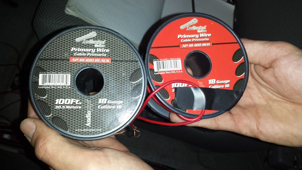
This thread is to show how I wired my Better Bed Lights in my 2007 Access Cab. If you haven't seen the bed lights yet check them out HERE.
DISCLAIMER: This is simply an explanation of how I wired my truck, I do not take any responsibility for any damage or destruction that you may cause in trying to replicate these steps. Your experience may differ and may not be the same for all years and models. Use this purely as reference and proceed at your own risk.
PART 1 - Getting the wires from the cab brake light to the dash
Step 1 - Remove the light.
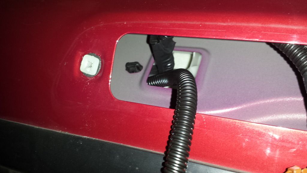
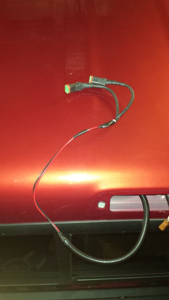
Remove the 2 screws from the cab brake light. They have a Torx T15 screw driver to do this. Firmly but gently peal the black bezel of the brake light away from the truck. The gasket has an adhesive on the light side as well as the truck side. Pulling the light off will most likely cause the gasket to rip but if you bought a Better Bed Light you don't have to worry because it comes with a new gasket. Once you get the light off (don't forget to unclip the brake wires) peal the old gasket off the truck and light bezel.
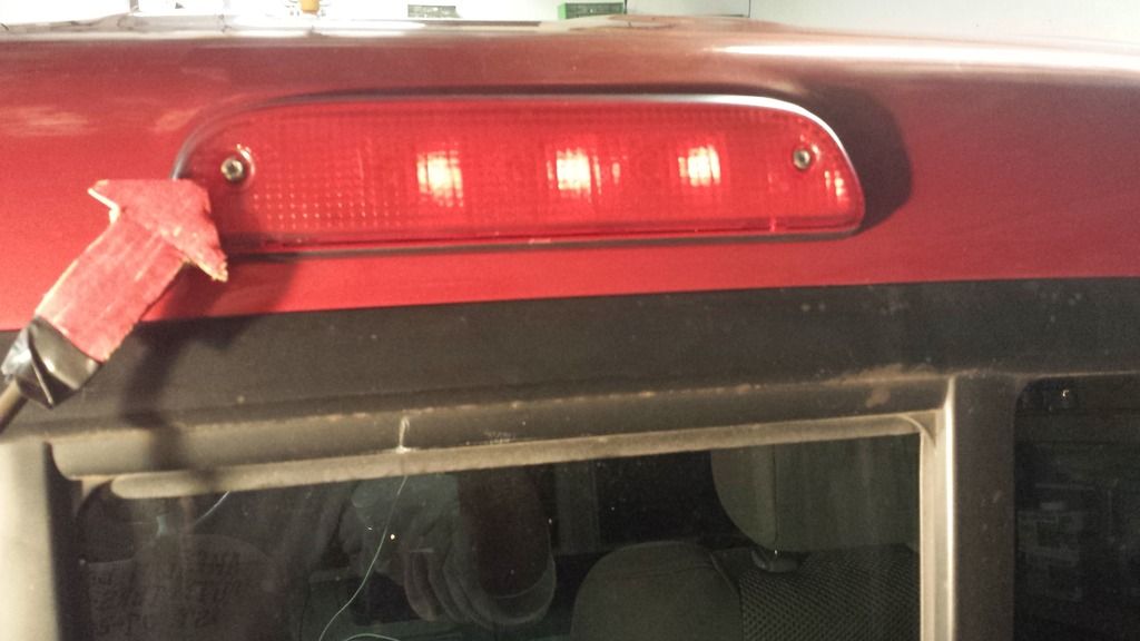
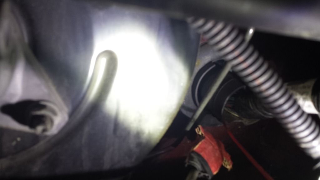
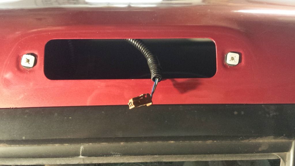
TADAH! Your truck should look something like this once you have pealed the old gasket off and disconnected the light.
Step 2 - Remove the ceiling molding on the driver side.
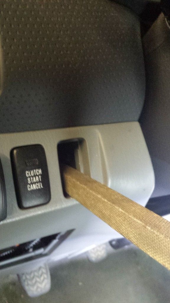
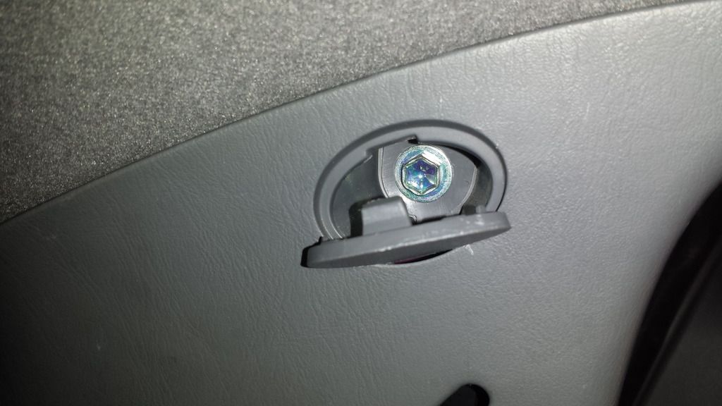
Open the driver side door and access cab door. Locate the two bolt cap covers on the plastic molding that wraps around the door latch. Gently pry them off. You can do this with your fingernails if they are long enough or by gently prying with a small flat edge, be careful not to mark up the plastic if you go the screw driver route!
Use a Torx T27 screw driver to remove the two bolts holding the molding on.
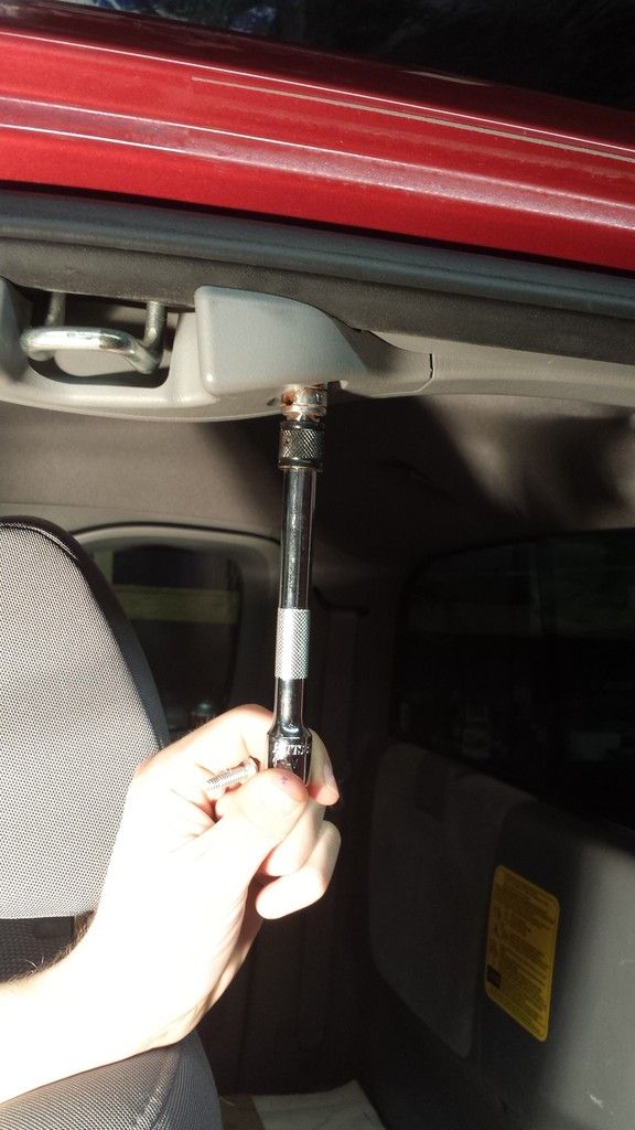
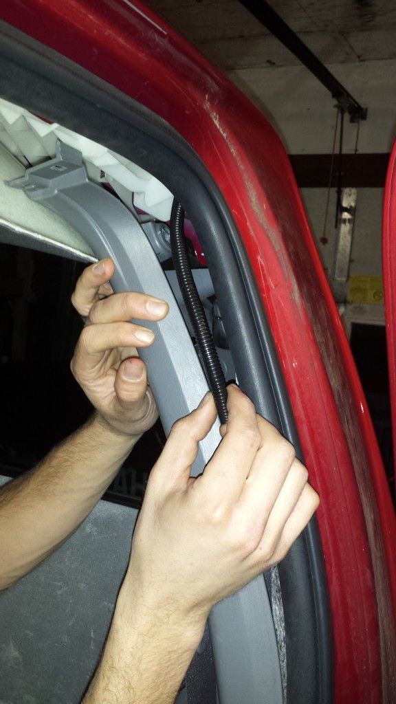
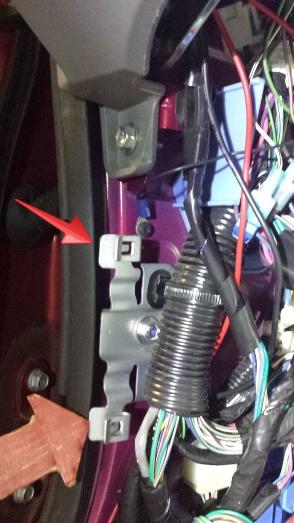
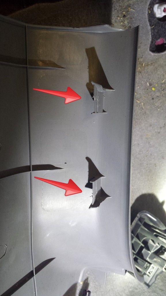
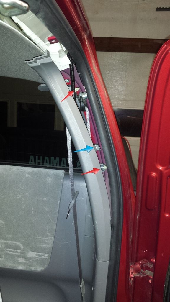
Once you remove the two bolts pull straight down firmly but carefully, the molding has a few retaining clips that hold it in in addition to 3 clips that hook around the weather stripping. Pull until the retaining clips let go but be careful of the 3 clips (see the red arrows) that hook onto the weather stripping. Work the molding free and pull it off.
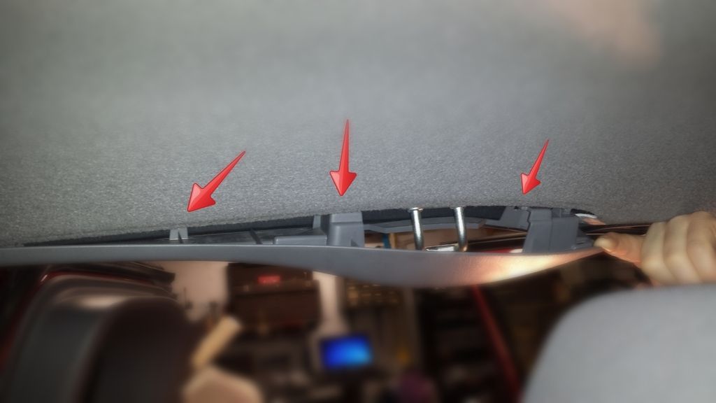
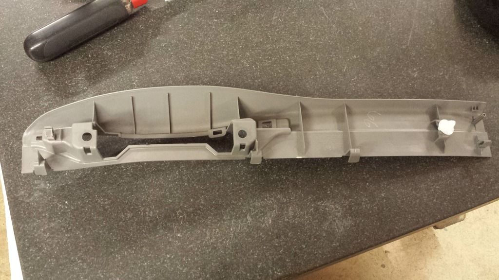
TADAH! again... This is what the underside of the plastic molding looks like. Note the white retaining clip and 3 gray hook type clips.
Step 3 - Loosen the rear driver side seat belt pannel.
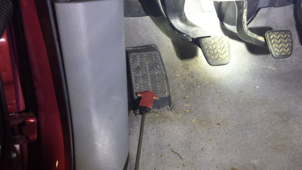
Locate the bolt cover over the seat belt and pry it off with either your fingernails or gently with a screw driver taking care not to make marks.
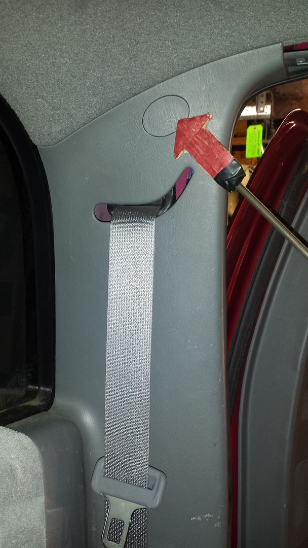
The cover stays attached revealing a 10mm bolt. Remove the 10mm bolt.
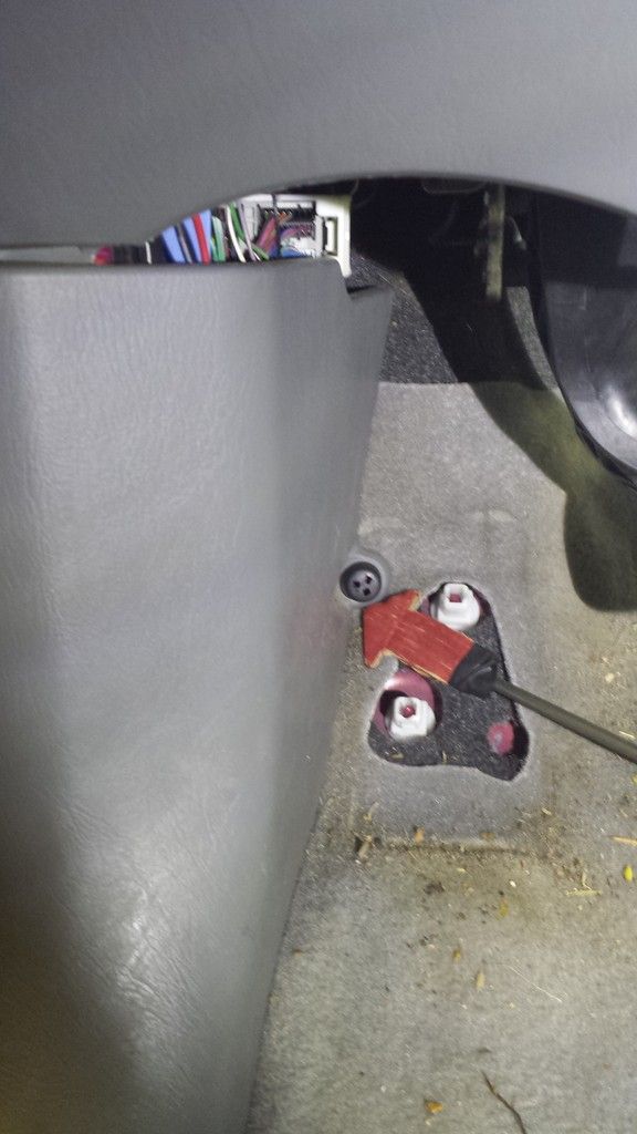
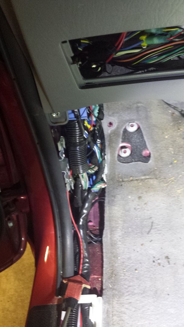
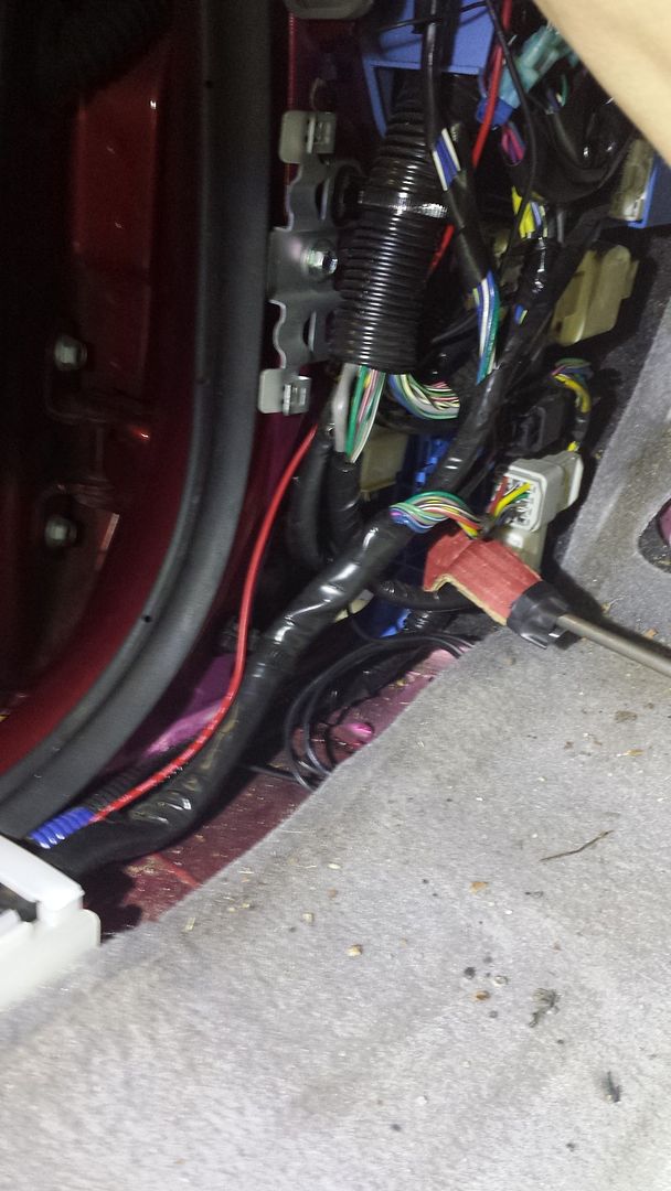
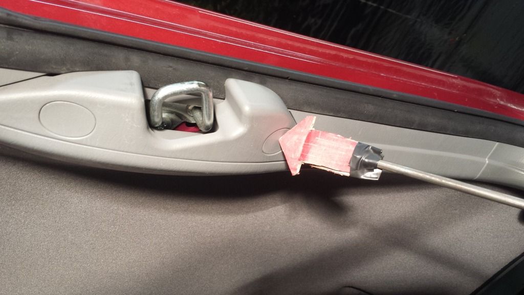
Pull straight away from the driver side wall, the retaining clips will pop out. Note there are 2 white retaining clips (red arrows) and 1 hook type clip that hooks onto the weather stripping. Be careful not to break the hook clip. You do not need to remove this entire panel just loosen it so you have enough space to access behind it like the picture below.
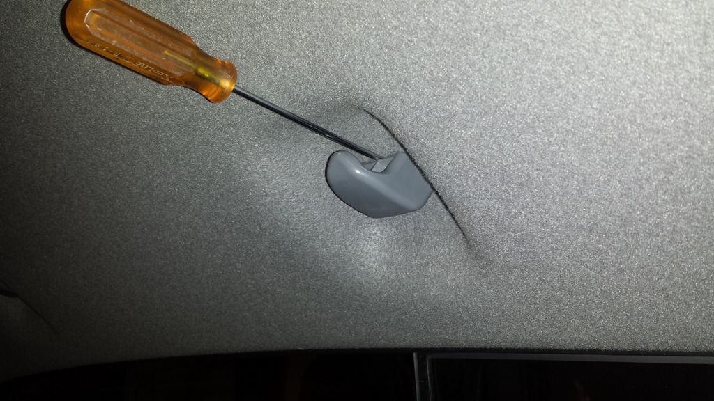
Step 4 - Remove the clothes hanger hooks.
Locate the two clothes hanger hooks.
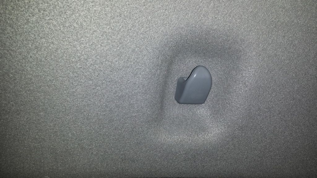
Locate the little notch at the top
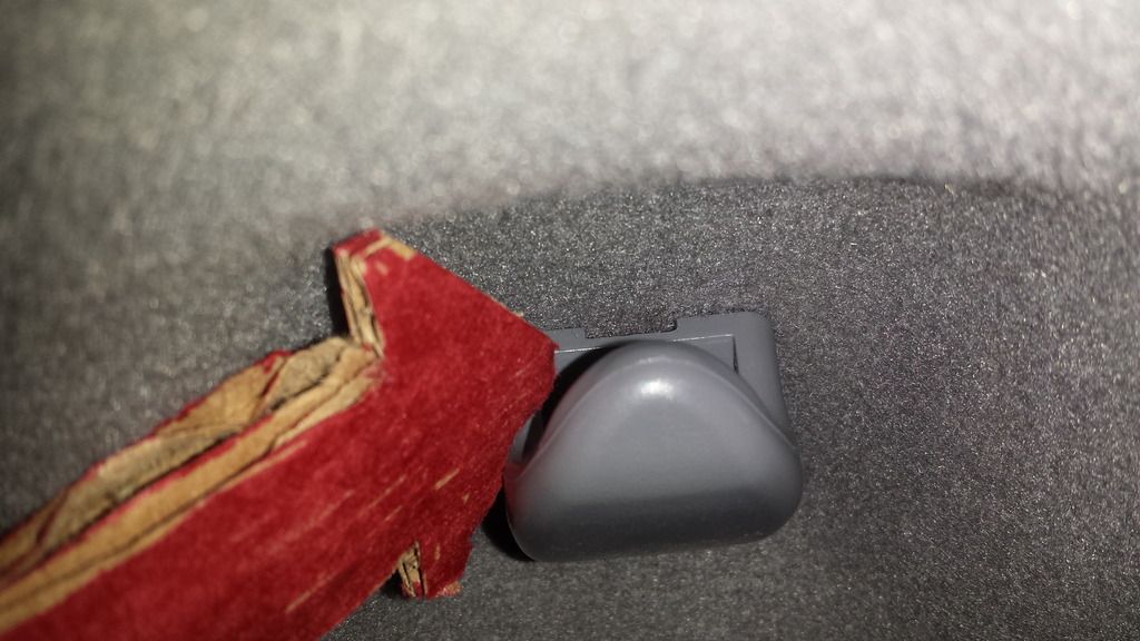
Stick a small flathead screwdriver in that notch and turn the hook a quarter turn counter-clockwise and gently pull it out.
Gently pull the headliner free in the back corner so you can access underneath it. This may take a little wiggling, but it isn't too hard if you are gentle and take your time. Notice the white ribs on the ceiling, remember those for later.... seriously remember them.
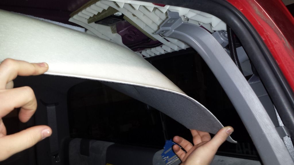
Did you remember the white ribs?:yay:Hooray!
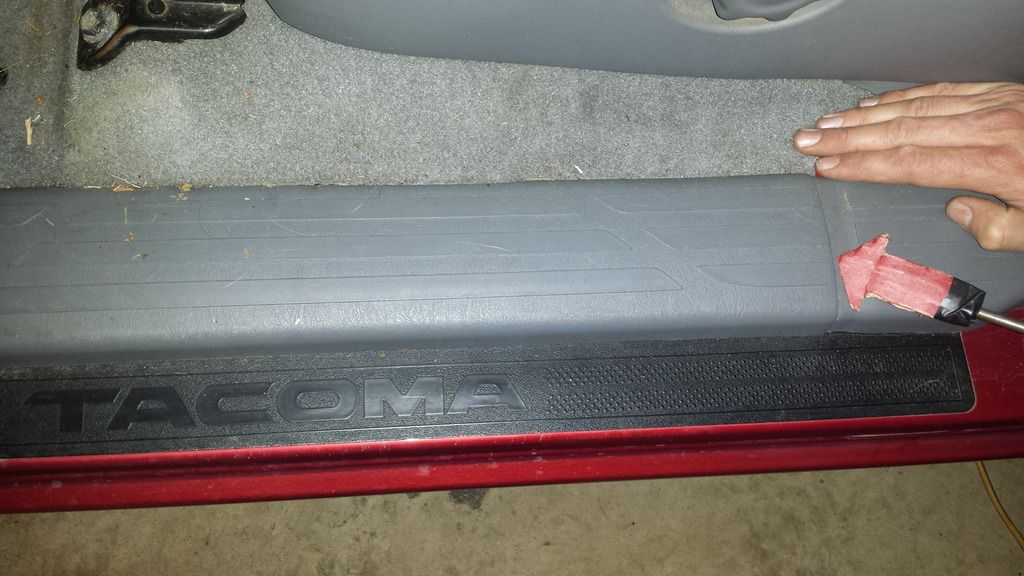
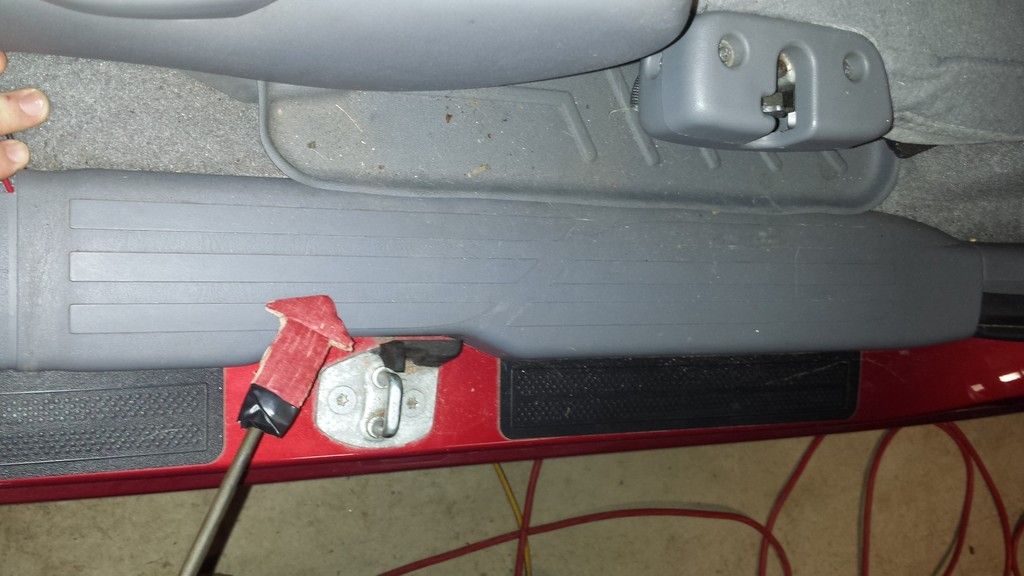
Step 5 - Remove the door jam panels
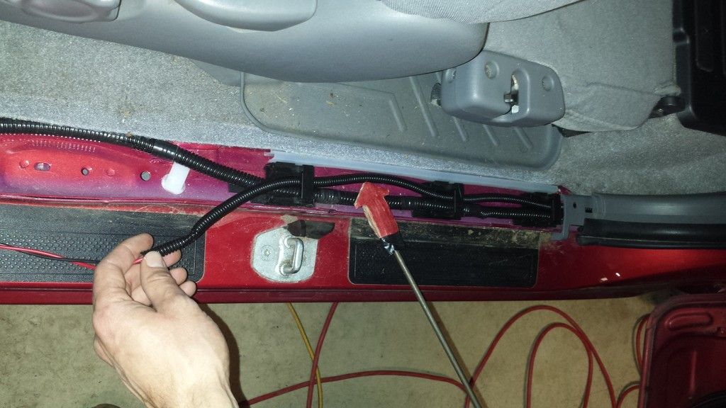
Locate the door jam panel under the driver side door. Pull straight up carefully and firmly starting at the back and working your way forward. There are several clips holding it in that will pull free as you do this.
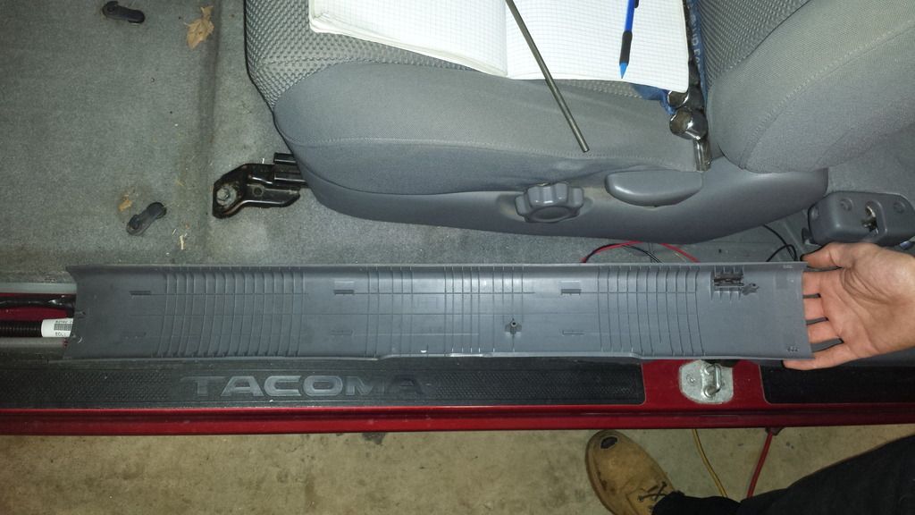
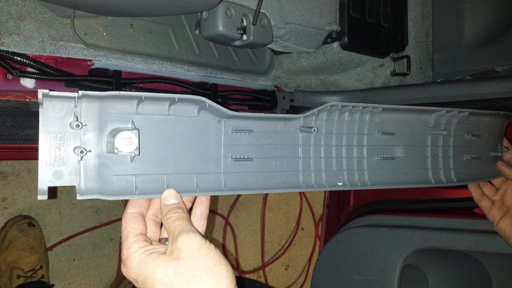
This is what the bottom of it looks like.
Locate the rear driver side door jam panel and pull straight up carefully and firmly but this time starting at the front.
Here is what the underside looks like
DISCLAIMER: This is simply an explanation of how I wired my truck, I do not take any responsibility for any damage or destruction that you may cause in trying to replicate these steps. Your experience may differ and may not be the same for all years and models. Use this purely as reference and proceed at your own risk.
PART 1 - Getting the wires from the cab brake light to the dash
Step 1 - Remove the light.
Remove the 2 screws from the cab brake light. They have a Torx T15 screw driver to do this. Firmly but gently peal the black bezel of the brake light away from the truck. The gasket has an adhesive on the light side as well as the truck side. Pulling the light off will most likely cause the gasket to rip but if you bought a Better Bed Light you don't have to worry because it comes with a new gasket. Once you get the light off (don't forget to unclip the brake wires) peal the old gasket off the truck and light bezel.
TADAH! Your truck should look something like this once you have pealed the old gasket off and disconnected the light.
Step 2 - Remove the ceiling molding on the driver side.
Open the driver side door and access cab door. Locate the two bolt cap covers on the plastic molding that wraps around the door latch. Gently pry them off. You can do this with your fingernails if they are long enough or by gently prying with a small flat edge, be careful not to mark up the plastic if you go the screw driver route!
Use a Torx T27 screw driver to remove the two bolts holding the molding on.
Once you remove the two bolts pull straight down firmly but carefully, the molding has a few retaining clips that hold it in in addition to 3 clips that hook around the weather stripping. Pull until the retaining clips let go but be careful of the 3 clips (see the red arrows) that hook onto the weather stripping. Work the molding free and pull it off.
TADAH! again... This is what the underside of the plastic molding looks like. Note the white retaining clip and 3 gray hook type clips.
Step 3 - Loosen the rear driver side seat belt pannel.
Locate the bolt cover over the seat belt and pry it off with either your fingernails or gently with a screw driver taking care not to make marks.
The cover stays attached revealing a 10mm bolt. Remove the 10mm bolt.
Pull straight away from the driver side wall, the retaining clips will pop out. Note there are 2 white retaining clips (red arrows) and 1 hook type clip that hooks onto the weather stripping. Be careful not to break the hook clip. You do not need to remove this entire panel just loosen it so you have enough space to access behind it like the picture below.
Step 4 - Remove the clothes hanger hooks.
Locate the two clothes hanger hooks.
Locate the little notch at the top
Stick a small flathead screwdriver in that notch and turn the hook a quarter turn counter-clockwise and gently pull it out.
Gently pull the headliner free in the back corner so you can access underneath it. This may take a little wiggling, but it isn't too hard if you are gentle and take your time. Notice the white ribs on the ceiling, remember those for later.... seriously remember them.
Did you remember the white ribs?:yay:Hooray!
Locate the door jam panel under the driver side door. Pull straight up carefully and firmly starting at the back and working your way forward. There are several clips holding it in that will pull free as you do this.
This is what the bottom of it looks like.
Locate the rear driver side door jam panel and pull straight up carefully and firmly but this time starting at the front.
Here is what the underside looks like